A structured cabling system consists of a number of components and subcomponents:
Horizontal wiring
It is a distribution system that runs horizontally between the ceiling and the floor. It contains the largest number of individual cables in the entire installation and is made up of two basic elements: routes and horizontal spaces that are responsible for, in addition to distributing and supporting the horizontal wiring, connecting the hardware between the exit of the work area and the room. telecommunications.
Its mission is to bring information from the distributor to the users. Its interior composition is mainly copper, therefore, it is important that it does not twist. Its location must be behind the walls so as not to have contact with it.
Vertical or backbone cabling
Also known as trunk cabling, it provides interconnections between building services, equipment rooms and telecommunications rooms. Makes the vertical connection between the different floors, establishing the transmission means, main and intermediate cross connection points and necessary mechanical terminations.
That is, it is responsible for establishing the interconnection between the different rooms or spaces. It is made up of vertical cables, cross connections, mechanical terminations and patch cords.
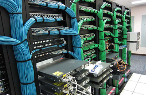
Communications room
It is the area designated exclusively to house the elements that make up the telecommunications infrastructure. That is, the room in which all the elements that make up the telecommunications system are housed and centralised: cables, connection accessories, protection devices… and other equipment necessary to connect the building to external services. It needs special characteristics to correctly fulfil its function.
Wiring service entrance room
It consists of cables, connection accessories, protection devices, and other equipment necessary to connect the building to external services. It can contain the demarcation point. They offer electric protection established by electric available codes. Specifically, they must be designed in accordance with the TIA/EIA-569-A standard. The installation requirements are:
Precautions in cable handling
Avoid tension on the cable
- Cables should not be routed in very tight groups
- Use appropriate cable routes and accessories 100 ohms UTP and ScTP
- Do not turn at an angle greater than 90 degrees
Grounding system
The grounding and bridging system established in standard ANSI/TIA/EIA-607 is an important component of any modern structured cabling system. The room must have a ground connection, connected to the general ground of the electrical installation, to make the connections of all equipment. This conduit is not always indicated on plans and may be unique for branches or circuits that pass through the same pass boxes, conduits or trays. Safety ground cables will be grounded underground.
Attenuation
Attenuation is the loss of signal due to distance from one point to another. Transmission signals over long distances are subject to distortion which is a loss of signal strength or amplitude. Attenuation is the main reason why the length of networks has several restrictions. If the signal becomes very weak, the receiving equipment will not intercept this information well or recognize it.
This causes errors, poor performance when having to retransmit the signal. Repeaters or amplifiers are used to extend network distances beyond the limitations of cable. Attenuation is measured with devices that inject a test signal into one end of the cable and measure it at the other end.
Read more 10 Home Staging Techniques To Sell A Flat Faster
Cable capacitance
Capacitance is the unit of measurement of the energy stored in a capacitor and the cable, having two or more electrodes separated by a dielectric material, basically behaves like a capacitor.
This unit can distort the signal in the cable: the longer the cable, and the thinner the thickness of the insulation, the greater the capacitance, which results in distortion.
Cable testers can measure the capacity of this torque to determine if the cable has been threaded or stretched. The capacitance of twisted pair cable in networks is between 17 and 20 pF.